Serial 2 S Complementer Shift Register
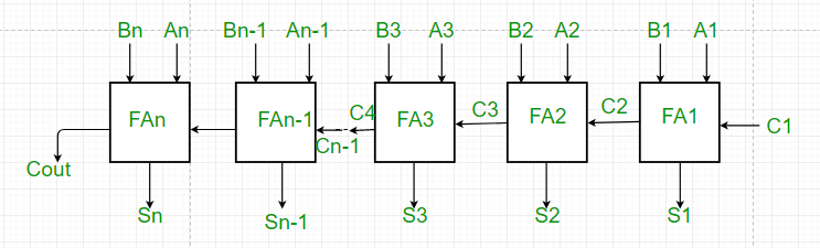

4- bit adder, 2's compliment subtractor circuit using a 4-bit adder IC. Verification of the operation of the circuit. Apparatus: Logic trainer kit, 4-bit adder (IC 7483), X-OR gates (IC 7486), wires Theory: IC 7483 is a 4 bit adder. Psp homebrew app store download pc. In binary, subtraction can be performed by using 2's complement method.
In this method negative number is converted into its 2's complement and it is added to the other number. The result of this addition is the subtraction of origin numbers.
If we modify the adder circuit, such that 2's complement and simple representation are presented, we can perform addition subtraction as required. X-OR gate is used as a controlled inverter/ buffer for this purpose. Use it as buffer for addition and inverter for subtraction. Procedure: 1. Connect the IC 7483 and IC 7486 as per diagram. Connect all A's and all B's to logic sources, S's to logic indicators. Connect Cin to logic 0, this will set the circuit for addition. Igru chtobi nauchitjsya ezditj na maschine.
Give various input combinations, verify adder operation. Here Cout is MSB of addition. Connect Cin to logic 1, this will set the circuit for subtraction by 2's complement method. Give various input combinations and observe outputs. Here Cout is neglected (2's complement subtraction) 7.
Design a serial 2's complementer using a shift register, a single DFF and minimum number of other gates. The binary number is shifted out from one side. 1 Answer to Design a 2's complementer with a shift register and a flip-flop. The binary # is shifted out from one side and it's 2's complement shifted into the other side of the shift register.
Switch off power supply. Aim: Verification of truth table for 7 segment decoder/ driver ICs Apparatus: Logic trainer kit, 7 segment decoder/ driver (IC 7447), wires Theory: Seven Segment is a display device. 7 LEDs are used in this device.
When a LED is forward biased, it emits light. By using a 7 segment, we can display various characters, formed by forward biased segments. It can be used to display 0-9 and a-F, BCD and Hexadecimal numbers can be displayed with it.
7 segment decoder/ driver is a combination of decoder circuit and display driver (for 7 segments). Input is given from 4 inputs and output is shown on display. Procedure: 1. Connect 4 inputs of display/ driver circuit to logic sources and switch on main supply. Give any combination to circuit. Observe the display; it should be according to BCD/ Hexadecimal encoding.
Give various input combinations, observe their corresponding outputs. Connect Cin to logic 1, this will set the circuit for subtraction by 2's complement method. Switch off power supply. Aim verfification of truth table for 8:1 multiplexer. Apparatus: Logic trainer kit, 8:1 multiplexer (IC 74151), wires Theory: A multiplexer (MUX) is an electronic circuit which has many inputs but only one output. It has some select lines, number of select lines is related to the number of inputs.